

QCC512x 与302X 蓝牙发射功率修改要用 PSkey,Bluecore内部有些配置寄存器,称为PSKEY,这些寄存器不可随意更改,当然也有些是可以自定义修改的。量产时经常在ADK 与 Application 中修改
qtil/ADK_QCC512X_QCC302X_WIN_6.4.0.43/doc/subsystem_config/bt_qcc512x_qcc302x.html
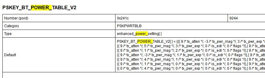
Bluetooth radio power table
This specifies the power table for later generation 40nm chips. This table contains an array of entries which configures the chip for a given output power, under both BDR and EDR conditions. It supersedes PSKEY_LC_POWER_TABLE, PSKEY_LC_ENHANCED_POWER_TABLE, PSKEY_BT_POWER_TABLE_V0 and PSKEY_BT_POWER_TABLE_V1.
The power table stored under this pskey provides a mapping between the settings of the various relevant hardware features, and the corresponding transmit power. This table is the basis for all of the firmware's transmit power control: LMP dynamic power control, PSKEY_LC_MAX_TX_POWER, PSKEY_LC_DEFAULT_TX_POWER, etc.
Every module design must have an appropriate power table. The default value suits the QTIL hardware; this is not suitable for other module designs.
The pskey's value is an array of "enhanced_power_setting" typed elements. The array's length is not fixed; typically an array is between 1 and 10 elements long.
The "enhanced_power_setting" type is a structure containing three entries: two power elements (one for basic rate, one for EDR), and a power level. The basic rate and EDR power elements have the same format, each contains: attenuation, magnitude, exponent, a reserved field, and a flags field. When represented as uint16's, these power elements pack into two uint16's as follows:
Word 1 (BR; or Word 3 for EDR): 1st nybble - attenuation 2nd nybble - magnitude 3rd nybble - exponent 4th nybble - reserved Word 2 (BR; or Word 4 for EDR): flags
The "magnitude" and "exponenent" function as (1 + Mag/16) / 2^Exp, where Exp = 0..3, and Mag is a signed 4-bit number.
The "attenuation" specifies the number of "segments" used, with 0 being the most (highest power) and 15 the least.
The reserved bits are used internally and should be zero in the PSKEY.
The flags field is described below.
The last word specifies the output power as a signed integer and is common to both data rates.
A power table is a list of these elements. The elements must be sequenced in ascending order of output power.
If the table contains only one element (of 3 uint16s) then the firmware will use those settings for all power levels.
The firmware responds to peer requests to increase/decrease transmit power by stepping up and down this table. The Bluetooth specification constrains the sizes and number of steps, which in turn bounds the size and content of the power table.
Bit 5 (corresponding to mask value 0x20) in the flags marks that entry to be "bypassed" from non-linearity correction. Since BR and LE signals are "constant envelope" this will not degrade preformance. EDR signals have significant power variation during a packet (during a single bit) and RF performance such as EVM will be significantly degraded if this bit is set for EDR.
In EDR operation, if the bottom bit of the flags field, Word 4 is set the power is marked as unavailable for EDR transmissions. Depending on the setting of BCCMD Limit_EDR_Power, the chip will either change the packet type table to basic rate; or refuse peer power control requests which request it to exceed the maximum allowed EDR power. If PSKEY_LC_DEFAULT_TX_POWER is greater than the maximum allowed EDR power, BlueCore will refuse to enter use EDR until the peer requests it to decrement its power sufficiently, after which it will attempt to change the packet type table to use EDR.
If any of the powers is marked as unavailable for EDR transmissions an equal number of powers have to be marked as unavailable for BR transmissions by setting bit 1 of the flags field, Word 4. This is to make sure that while talking to devices that don't support enhanced power control (EPC), the power table has an equal number of power steps for both BR and EDR. Note: If the maximum transmit power has been modified via PSKEY_LC_MAX_TX_POWER or the VM trap VmTransmitPowerSetMaximum then care must be taken to ensure that the number of powers marked as unavailable for EDR transmissions is still equal to the number of powers marked as unavailable for BR transmissions.
The powertable entries must start with the lowest output power and increase in power from each entry to the next.
If there are more than four distinct 'tx_atten' values in the EDR power table the device will fault with, FAULT_INVALID_EDR_POWERTABLE_ATTENUATION.
See PSKEY_BT_POWER_TABLE_V1, PSKEY_BT_POWER_TABLE_V0, PSKEY_LC_MAX_TX_POWER, PSKEY_LC_DEFAULT_TX_POWER, PSKEY_LOCAL_SUPPORTED_FEATURES PSKEY_TRANSMIT_OFFSET.
可以将PSKEY_BT_POWER_TABLE_V2加入到HTF文件中
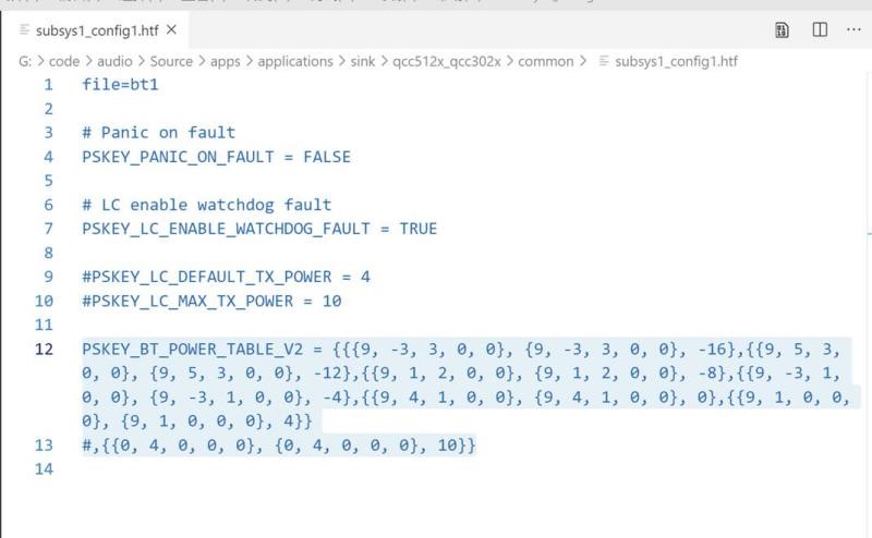
power table 表默认分了七组,由小到大,耳机用最底下的那组功率,不建议配置
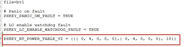
如上修改power table 固定10db,实测能达8db.功率达到最大,距离最远了!
如果距离没有明显提升,还是不要修改这个表格。
评论