

一、UTick 简介
1.1 结构框图
Micro-Tick Timer ( UTICK ) 是一个 31 位的定时器,计数到 0 会产生一个中断,从而提供一个固定的中断之间的时间间隔。UTICK是一个简单的,超低功耗定时器,可以在任何低功耗模式下运行和唤醒设备,包括深度掉电模式。
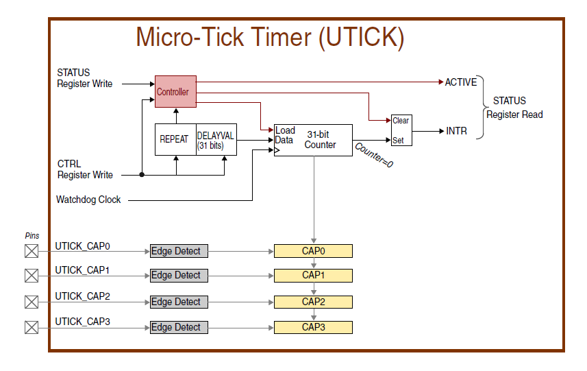 图 1. UTick 结构框图
UTick 可在任何电源模式下唤醒设备,中断可设为一次或重复中断,带有 4 个捕获寄存器,可以触发外部引脚转换。
二、UTick 使用
这里我们以 i.MX RT500 EVK 的 UTick 定时唤醒 DeepSleep 模式下的 MCU 为例,介绍如何使用 Utick。
2.1 初始化 UTick
开启时钟,这里使用的是 LPOSC 的 1MHz 的时钟源,初始化 UTick 定时器,主要包含使能中断等操作,如下图。

图 2. 初始化 UTick
2.2 启用 DeepSleep 模式的 UTick 唤醒中断
启用 UTick 定时器从深度睡眠模式中唤醒的中断,如下图所示。

图 3. 启用深度睡眠 UTick 唤醒中断
2.3 设置中断时间和模式
设置中断模式,这里我们是用重复中断,中断时间 10ms ,设置回调函数为 UTickCallback() ,回调内容用户可自定义,比如置位标志位等,如下图。

图 4. 设置 UTick
这里需要注意的是,设置完之后,UTick 就开始计时了,写完中断时间就会启用定时器,如果设置中断时间为 0,则会停止计时器。
2.4 设置进入 DeepSleep 后开启 LPOSC 时钟
设置 DeepSleep 模式下 时钟源 LPOSC 的工作状态,由于我们 UTick 使用此时钟源,所以在 DeepSleep 时要开启它,这个可以在 Power API 中设置,如下图。

图 5. POWER_EnterDeepSleep()
此设置直接更改函数 POWER_EnterDeepSleep() 的入口参数 APP_EXCLUDE_FROM_DEEPSLEEP 即可实现,如下图。

图 6. DeepSleep 时开启 LPOSC
接下来,就可以验证我们的代码,运行后串口打印如下:

图 7. 运行现象
三、实验代码
/*
 * Copyright (c) 2016, Freescale Semiconductor, Inc.
 * Copyright 2016-2020 NXP
 * All rights reserved.
 *
 * SPDX-License-Identifier: BSD-3-Clause
 */

#include "fsl_debug_console.h"
#include "pin_mux.h"
#include "clock_config.h"
#include "board.h"
#include "fsl_common.h"
#include "fsl_power.h"
#include "fsl_inputmux.h"
#include "fsl_pint.h"
#include "fsl_usart.h"
#include "fsl_utick.h"	//增加,20210915
#include "pmic_support.h"

#include "fsl_pca9420.h"
/*******************************************************************************
 * Definitions
 ******************************************************************************/
/*
 * The option is used for measurement of the deep sleep wake-up latency. When the application calls
 * POWER_EnterDeepSleep(), the power library will control the PLL power depending on the
 * exclude_from_pd parameter and the PLL running status. If the PLL is not in the exclude_from_pd list
 * and is running, it will be powered off before WFI and restored after WFI by the power library. Otherwise,
 * the PLL control will not be changed in POWER_EnterDeepSleep().
 * As the PLL initialization costs time to stabilize the clock, user will see the duration of
 * POWER_EnterDeepSleep() is longer than expectation.
 * To get rid of the PLL clock initialization time from deep sleep wake-up latency measurement, we can set
 * POWER_DOWN_PLL_BEFORE_DEEP_SLEEP to 1, then the demo itself will disable the PLL before
 * calling POWER_EnterDeepSleep(), and restore PLL after that. Thus we get the real duration of system
 * deep sleep wake-up time.
 */
#define POWER_DOWN_PLL_BEFORE_DEEP_SLEEP \
    0 /* By default, we keep the application as simple as possible to make good OOBE. */

#define APP_USART_RX_ERROR               kUSART_RxError
#define APP_USER_WAKEUP_KEY_NAME         "SW2"
#define APP_USER_WAKEUP_KEY_GPIO         GPIO
#define APP_USER_WAKEUP_KEY_PORT         0
#define APP_USER_WAKEUP_KEY_PIN          10
#define APP_USER_WAKEUP_KEY_INPUTMUX_SEL kINPUTMUX_GpioPort0Pin10ToPintsel
/*!< Power down all unnecessary blocks and enable RBB during deep sleep. */
#define APP_DEEPSLEEP_RUNCFG0 (SYSCTL0_PDRUNCFG0_RBBSRAM_PD_MASK | SYSCTL0_PDRUNCFG0_RBB_PD_MASK)
#define APP_DEEPSLEEP_RAM_APD 0x00FFF000U /* 0x80000 - 0x2FFFFF keep powered */
#define APP_DEEPSLEEP_RAM_PPD 0x0U
#define APP_EXCLUDE_FROM_DEEPSLEEP                                                                           \
    (((const uint32_t[]){(APP_DEEPSLEEP_RUNCFG0 | SYSCTL0_PDSLEEPCFG0_LPOSC_PD_MASK),                                                              \
                         (SYSCTL0_PDSLEEPCFG1_FLEXSPI0_SRAM_APD_MASK | SYSCTL0_PDSLEEPCFG1_SRAM_SLEEP_MASK), \
                         APP_DEEPSLEEP_RAM_APD, APP_DEEPSLEEP_RAM_PPD}))

#define APP_EXCLUDE_FROM_DEEP_POWERDOWN      (((const uint32_t[]){0, 0, 0, 0}))
#define APP_EXCLUDE_FROM_FULL_DEEP_POWERDOWN (((const uint32_t[]){0, 0, 0, 0}))
const char *gWakeupInfoStr[] = {"Sleep [Press the user key to wakeup]", "Deep Sleep [Press the user key to wakeup]",
                                "Deep Powerdown [Reset to wakeup]", "Full Deep Powerdown [Reset to wakeup]"};
uint32_t gCurrentPowerMode;
volatile bool pintFlag = false;


static volatile bool utickExpired;	//增加,20210915
/*******************************************************************************
 * Prototypes
 ******************************************************************************/
void BOARD_ConfigPMICModes(pca9420_modecfg_t *cfg, uint32_t num);
static uint32_t APP_GetUserSelection(void);
static void APP_InitWakeupPin(void);
static void pint_intr_callback(pint_pin_int_t pintr, uint32_t pmatch_status);
static void APP_InitWakeupUTick(void);	//增加,20210915
static void UTickCallback(void);	//增加,20210915
static void UTickSet(uint32_t usec);	//增加,20210915
/*******************************************************************************
 * Code
 ******************************************************************************/
/*PLL status*/
extern const clock_sys_pll_config_t g_sysPllConfig_BOARD_BootClockRUN;
extern const clock_audio_pll_config_t g_audioPllConfig_BOARD_BootClockRUN;
AT_QUICKACCESS_SECTION_CODE(void BOARD_SetFlexspiClock(FLEXSPI_Type *base, uint32_t src, uint32_t divider));


void BOARD_ConfigPMICModes(pca9420_modecfg_t *cfg, uint32_t num)
{
    assert(cfg);

    /* Configuration PMIC mode to align with power lib like below:
     *  0b00    run mode, no special.
     *  0b01    deep sleep mode, vddcore 0.6V.
     *  0b10    deep powerdown mode, vddcore off.
     *  0b11    full deep powerdown mode vdd1v8 and vddcore off. */

    /* Mode 1: VDDCORE 0.6V. */
    cfg[1].sw1OutVolt = kPCA9420_Sw1OutVolt0V600;
    /* Mode 2: VDDCORE off. */
    cfg[2].enableSw1Out = false;

    /* Mode 3: VDDCORE, VDD1V8 and VDDIO off. */
    cfg[3].enableSw1Out  = false;
    cfg[3].enableSw2Out  = false;
    cfg[3].enableLdo2Out = false;
}

/*!
 * @brief Main function
 */
int main(void)
{
    /* Define the init structure for the output LED pin*/
    gpio_pin_config_t led_config = {	//增加,20210915
        kGPIO_DigitalOutput,
        0,
    };

    /* Init board hardware. */
    pca9420_modecfg_t pca9420ModeCfg[4];
    uint32_t i;

    /* BE CAUTIOUS TO SET CORRECT VOLTAGE RANGE ACCORDING TO YOUR BOARD/APPLICATION. PAD SUPPLY BEYOND THE RANGE DO
       HARM TO THE SILICON. */
    power_pad_vrange_t vrange = {.Vdde0Range = kPadVol_171_198,
                                 .Vdde1Range = kPadVol_171_198,
                                 .Vdde2Range = kPadVol_171_198,
.Vdde3Range = kPadVol_300_360,
.Vdde4Range = kPadVol_171_198};
BOARD_InitPins();
BOARD_BootClockRUN();
BOARD_InitDebugConsole();
//------------------------------------------- LED -------------------------------------------
GPIO_PortInit(GPIO, 3U);
GPIO_PinInit(GPIO, 3U, 17U, &led_config); //增加,20210915
GPIO_PinWrite(GPIO, 3U, 17U, 1);
/* PMIC PCA9420 */
BOARD_InitPmic();
for (i = 0; i < ARRAY_SIZE(pca9420ModeCfg); i++)
{
PCA9420_GetDefaultModeConfig(&pca9420ModeCfg[i]);
}
BOARD_ConfigPMICModes(pca9420ModeCfg, ARRAY_SIZE(pca9420ModeCfg));
PCA9420_WriteModeConfigs(&pca9420Handle, kPCA9420_Mode0, &pca9420ModeCfg[0], ARRAY_SIZE(pca9420ModeCfg));
/* Configure PMIC Vddcore value according to CM33 clock. DSP not used in this demo. */
BOARD_SetPmicVoltageForFreq(CLOCK_GetFreq(kCLOCK_CoreSysClk), 0U);
/* Indicate to power library that PMIC is used. */
POWER_UpdatePmicRecoveryTime(1);
POWER_SetPadVolRange(&vrange);
/* Determine the power mode before bring up. */
if ((POWER_GetEventFlags() & PMC_FLAGS_DEEPPDF_MASK) != 0)
{
PRINTF("Board wake up from deep or full deep power down mode.\r\n");
POWER_ClearEventFlags(PMC_FLAGS_DEEPPDF_MASK);
}
APP_InitWakeupPin();
//------------------------------------------- UTick -------------------------------------------
APP_InitWakeupUTick(); //增加,20210915
PRINTF("Power Manager Demo.\r\n");
PRINTF("The \"user key\" is: %s\r\n\r\n", APP_USER_WAKEUP_KEY_NAME);
gCurrentPowerMode = APP_GetUserSelection(); //测试
PRINTF("Entering %s ...\r\n", gWakeupInfoStr[gCurrentPowerMode]);
while (1)
{
// gCurrentPowerMode = APP_GetUserSelection(); //测试 //屏蔽,20210915
// PRINTF("Entering %s ...\r\n", gWakeupInfoStr[gCurrentPowerMode]);
// pintFlag = false;
/* Enter the low power mode. */
switch (gCurrentPowerMode)
{
case kPmu_Sleep: /* Enter sleep mode. */
PRINTF("Entering Sleep...\r\n");
PRINTF("UTick = 2000ms.\r\n");
UTickSet(2000000); //2000ms //增加,20210915
POWER_EnterSleep();
break;
case kPmu_Deep_Sleep: /* Enter deep sleep mode. */
PRINTF("Entering Deep Sleep...\r\n");
PRINTF("UTick = 2000ms.\r\n");
UTickSet(2000000); //2000ms //增加,20210915
BOARD_SetPmicVoltageBeforeDeepSleep();
#if POWER_DOWN_PLL_BEFORE_DEEP_SLEEP
/* Disable Pll before enter deep sleep mode */
BOARD_DisablePll();
#endif
POWER_EnterDeepSleep(APP_EXCLUDE_FROM_DEEPSLEEP);
#if POWER_DOWN_PLL_BEFORE_DEEP_SLEEP
/* Restore Pll before enter deep sleep mode */
BOARD_RestorePll();
#endif
BOARD_RestorePmicVoltageAfterDeepSleep();
break;
case kPmu_Deep_PowerDown: /* Enter deep power down mode. */
PRINTF(
"Press any key to confirm to enter the deep power down mode and wakeup the device by "
"reset.\r\n\r\n");
GETCHAR();
BOARD_SetPmicVoltageBeforeDeepPowerDown();
POWER_EnterDeepPowerDown(APP_EXCLUDE_FROM_DEEP_POWERDOWN);
/* After deep power down wakeup, the code will restart and cannot reach here. */
break;
case kPmu_Full_Deep_PowerDown: /* Enter full deep power down mode. */
PRINTF(
"Press any key to confirm to enter the full deep power down mode and wakeup the device by "
"reset.\r\n\r\n");
GETCHAR();
BOARD_SetPmicVoltageBeforeDeepPowerDown();
POWER_EnterFullDeepPowerDown(APP_EXCLUDE_FROM_FULL_DEEP_POWERDOWN);
/* After full deep power down wakeup, the code will restart and cannot reach here. */
break;
default:
break;
}
if (pintFlag)
{
PRINTF("Pin event occurs\r\n");
pintFlag = false; //增加,20210915
PRINTF("UTick = 0.\r\n"); //增加,20210915
UTickSet(0); //0ms
PRINTF("Wakeup.\r\n");
gCurrentPowerMode = 4; //测试 //增加,20210915
}
if (utickExpired) //增加,20210915
{
PRINTF("Utick event occurs\r\n");
utickExpired = false; //增加,20210915
PRINTF("UTick = 0.\r\n");
UTickSet(0); //0ms
PRINTF("Wakeup.\r\n");
gCurrentPowerMode = 4; //测试 //增加,20210915
}
//------------------------------------------- LED -------------------------------------------
PRINTF("LED Toggle\r\n");
GPIO_PortToggle(GPIO, 3U, 1u << 17U); //增加,20210915
for(int32_t i = 10000*1000; i>0; --i)
{
}
}
}
/*
* Setup a GPIO input pin as wakeup source.
*/
static void APP_InitWakeupPin(void)
{
gpio_pin_config_t gpioPinConfigStruct;
/* Set SW pin as GPIO input. */
gpioPinConfigStruct.pinDirection = kGPIO_DigitalInput;
GPIO_PinInit(APP_USER_WAKEUP_KEY_GPIO, APP_USER_WAKEUP_KEY_PORT, APP_USER_WAKEUP_KEY_PIN, &gpioPinConfigStruct);
/* Configure the Input Mux block and connect the trigger source to PinInt channle. */
INPUTMUX_Init(INPUTMUX);
INPUTMUX_AttachSignal(INPUTMUX, kPINT_PinInt0, APP_USER_WAKEUP_KEY_INPUTMUX_SEL); /* Using channel 0. */
INPUTMUX_Deinit(INPUTMUX); /* Turnoff clock to inputmux to save power. Clock is only needed to make changes */
/* Configure the interrupt for SW pin. */
PINT_Init(PINT);
PINT_PinInterruptConfig(PINT, kPINT_PinInt0, kPINT_PinIntEnableFallEdge, pint_intr_callback);
PINT_EnableCallback(PINT); /* Enable callbacks for PINT */
EnableDeepSleepIRQ(PIN_INT0_IRQn);
}
static void APP_InitWakeupUTick(void) //增加, 20210915
{
/* Init board hardware. */
CLOCK_AttachClk(kLPOSC_to_UTICK_CLK);
/* Intiialize UTICK */
UTICK_Init(UTICK0);
EnableDeepSleepIRQ(UTICK0_IRQn);
}
static void UTickSet(uint32_t usec) //增加, 20210915
{
/* Set the UTICK timer to wake up the device from reduced power mode */
UTICK_SetTick(UTICK0, kUTICK_Repeat, usec - 1, UTickCallback); //kUTICK_Onetime
utickExpired = false;
}
static void UTickCallback(void) //增加, 20210915
{
PRINTF("UTickCallback\r\n"); //测试
utickExpired = true;
}
/*
* Callback function when wakeup key is pressed.
*/
static void pint_intr_callback(pint_pin_int_t pintr, uint32_t pmatch_status)
{
pintFlag = true;
}
/*
* Get user selection from UART.
*/
static uint32_t APP_GetUserSelection(void)
{
uint32_t ch = 0;
/* Clear rx overflow error once it happens during low power mode. */
if (APP_USART_RX_ERROR == (APP_USART_RX_ERROR & USART_GetStatusFlags((USART_Type *)BOARD_DEBUG_UART_BASEADDR)))
{
USART_ClearStatusFlags((USART_Type *)BOARD_DEBUG_UART_BASEADDR, APP_USART_RX_ERROR);
}
PRINTF(
"Select an option\r\n"
"\t1. Sleep mode\r\n"
"\t2. Deep Sleep mode\r\n"
"\t3. Deep power down mode\r\n"
"\t4. Full deep power down mode\r\n");
while (1)
{
ch = GETCHAR();
if ((ch < '1') || (ch > '4')) /* Only '1', '2', '3' , '4'. */
{
continue;
}
else
{
ch = ch - '1'; /* Only 0, 1, 2 , 3 . */
break;
}
}
switch (ch)
{
case 0:
ch = kPmu_Sleep;
break;
case 1:
ch = kPmu_Deep_Sleep;
break;
case 2:
ch = kPmu_Deep_PowerDown;
break;
case 3:
ch = kPmu_Full_Deep_PowerDown;
break;
default:
break;
}
return ch;
}
四、参考资料
(1)i.MX RT500 系列相关资料均可在 NXP 官网下载,网址如下: