

1.概述
2.ACMP 比较器信号连接
3.ACMP 比较器初始化代码
4.CTIMER 初始化代码
5.CTIMER 中断保存捕获值
6.速度计算
7.测试与验证
8.参考资料
- 概述
在 BLDC 电机无感方波控制中,除了使用反电动势来估计转子位置外,还可以用来测量电机转子的速度,提供给速度环做速度闭环控制,正常情况下其中一相的反电动势波形如下图所示,如果能连续测量两相之间的反电动势过零点之间的时间,则电机转子的转速即可计算出来,本例中使用 LPC845 的 CTIMER 捕获两次反电动势过零点之间的 counter 值,再根据 CTIMER 的运行频率即可计算出时间。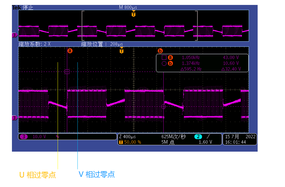
- ACMP 比较器信号连接
LPC845 内部集成了一个比较器,其负向端连接母线电压分压后并再经过 ACMP 比较器内部的阶梯分压后的信号,正向端连接相线并分压后的电压信号,当正向端大于或小于负向端时将产生正向过零信号和负向过零信号,此信号再连接至 CTIMER 的输入引脚,触发 CTIMER 产生捕获,记录下两次过零信号之间的 counter 值(电机转子旋转 60 度的时间),从而计算出电机转子转速。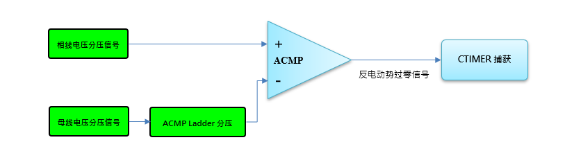
- ACMP 比较器初始化代码
ACMP 配置为:打开电源、使能时钟、复位、信号选择、使能中断、滞回电压、阶梯电压选择,如下代码所示:
void ACMP_init(void)
{
  /* ACMP Power Enable */
  SYSCON->PDRUNCFG &= ~(1 << 15);

  /* ACMP clk enable*/
  SYSCON->SYSAHBCLKCTRL0 |= (1 << 19);

  /* ACMP Reset */
  SYSCON->PRESETCTRL0 &= ~(1 << 19);
  SYSCON->PRESETCTRL0 |=  (1 << 19);

  ACOMP->CTRL = 0;
  ACOMP->CTRL = (uint32_t)((0x02 << 3 )  /* EDGESEL        0 Falling,0x1 Rising,0x2 Both */
                          |(   1 << 6 )  /* COMPSA         0 output directly */
                          |( 0x1 << 8 )  /* COMP_VP_SEL    0 ladder output,1 IN1 ... 5 IN5,6 band gap,7 DACOUT */
                          |( 0x0 << 11)  /* COMP_VM_SEL    0 ladder output,1 IN1 ... 5 IN5,6 band gap,7 DACOUT */
                          |(   1 << 20)  /* EDGECLR           write 1 to clear */
                          |(   1 << 24)  /* INTENA         1  Interrupt Enable */
                          |(   3 << 25)  /* HYS            0 None,1 5mV,2 10mV,3 20mV  hysteresis */
                           );
  ACOMP->LAD  = 0;
  ACOMP->LAD  = (uint32_t)((    1 << 0)  /* LADEN */
                          |( 0x12 << 1)  /* LADSEL  0 VSS 1 1xVref/31 ... 11111 = Vref */
                          |(    1 << 6)  /* LADREF  0 VDD,1 VDDCMP */
                           );
NVIC_SetPriority (CMP_CAPT_IRQn, 0);
NVIC_EnableIRQ(CMP_CAPT_IRQn);
}
- CTIMER 初始化代码
CTIMER 只需要在接收到触发信号时捕获 counter 值即可,其模式设置为捕获功能,功能单一,主要设置 CTCR 寄存器的 0 位为 0,即每个系统时钟计数模式,通道 0 作为输入触发捕获信号,为保证上电后寄存器都处于确定值,都重新设置一遍,如下代码所示:
void ctimer_init(void)
{
  /* Reset CTIMER*/
  SYSCON->PRESETCTRL0 &= ~(1 << 25);
  SYSCON->PRESETCTRL0 |=  (1 << 25);

  SYSCON->SYSAHBCLKCTRL0 |= (1 << 25);/* CTIMER clk enable*/

  // Configure the Count Control register
  CTIMER0->CTCR = 0;
  CTIMER0->CTCR = (uint32_t)( (0 << 0)     /*       Mode: 0x0  Timer Mode,Incremented every rising APB bus clock edge.
                                                          0x1  Counter Mode rising edge.
                                                          0x2  Counter Mode falling edge.
                                                          0x3  Counter Mode dual edge.
                                            */
                             |(0 << 2)     /* CINSEL    :When not Timer Mode,Count Input Select, 0x0 Channel 0 CAP0
                                                                                                 0x1 Channel 1 CAP1
                                                                                                 0x2 Channel 2 CAP2 */
                             |(1 << 4)     /* ENCC      :Setting this bit to 1 enables clearing of the timer and the prescaler */
                             |(0 << 5));   /* SELCC     :Edge select, When bit 4 is 1, these bits select which capture input edge will cause the
                                                         timer and prescaler to be cleared.
                                                         0 Rising edge of the signal on capture channel 0 clears the timer
                                                         1 Falling edge of the signal on capture channel 0 clears the timer */


  CTIMER0->TC   = 0;  //Timer counter value
  CTIMER0->PR   = 0;  //Prescale counter value
  CTIMER0->PC   = 0;  //Prescale Counter

  //------------------------------------------ Capture ------------------------------------------------------------------

  CTIMER0->CCR  = 0;  //Capture Control Register
  CTIMER0->CCR  = (uint32_t)( (1 << 0)     /* CAP0RE: Rising edge of capture channel 0 */
                             |(1 << 1)     /* CAP0FE: Falling edge of capture channel 0 */
                             |(0 << 2)     /* CAP0I:  Generate interrupt on channel 0 capture event */
                             |(0 << 3)     /* CAP1RE: Rising edge of capture channel 0 */
                             |(0 << 4)     /* CAP1FE: Falling edge of capture channel 0 */
                             |(0 << 5)     /* CAP1I:  Generate interrupt on channel 0 capture event */
                             |(0 << 6)     /* CAP2RE: Rising edge of capture channel 0 */
                             |(0 << 7)     /* CAP2FE: Falling edge of capture channel 0 */
                             |(0 << 8)     /* CAP2I:  Generate interrupt on channel 0 capture event */
                             |(0 << 9)     /* CAP3RE: Rising edge of capture channel 0 */
|(0 << 10) /* CAP3FE: Falling edge of capture channel 0 */
|(0 << 11)); /* CAP3I: Generate interrupt on channel 0 capture event */
//------------------------------------------ Match --------------------------------------------------------------------
CTIMER0->EMR = 0; /* EM0/EM1/EM2/EM3: This bit reflects the state of output MATX
The External Match Register provides both control and status of the external match pins
EMC0/EMC1/EMC2/EMC3: External Match Control X. Determines the functionality of External Match X.
0x0 Do Nothing.
0x1 Clear,Pin Low
0x2 Set, Pin High
0x3 Toggle.
*/
CTIMER0->PWMC = 0; /*PWMEN0/PWMEN1/PWMEN2/PWMEN3: 0 Match. CTIMER_MAT0 is controlled by EM0
1 PWM. PWM mode is enabled for CTIMER_MAT0.
if MAT2 or MAT1 or MAT0 match,output High, MAT3 match set all Low */
CTIMER0->MR[0] = 0xFFFFFFFF; /* Match Registers */
CTIMER0->MR[1] = 0xFFFFFFFF; /* Match Registers */
CTIMER0->MR[2] = 0xFFFFFFFF; /* Match Registers */
CTIMER0->MR[3] = 0xFFFFFFFF; /* Match Registers */
CTIMER0->MSR[0] = 0xFFFFFFFF; /* Match Shadow Registers, Match Registers are reloaded with at the start of each new counter cycle */
CTIMER0->MSR[0] = 0xFFFFFFFF;
CTIMER0->MSR[0] = 0xFFFFFFFF;
CTIMER0->MSR[0] = 0xFFFFFFFF;
/* Match Control Register
0 Interrupt on MR0: an interrupt is generated when MR0 matches the value in the TC
1 Reset on MR0: the TC will be reset if MR0 matches it
2 Stop on MR0: the TC and PC will be stopped and TCR[0] will be set to 0 if MR0 matches the TC
24 Reload MR0 with the contents of the Match 0 Shadow Register when the TC is reset to zero
*/
CTIMER0->MCR = 0;
//------------------------------------------ Match --------------------------------------------------------------------
// Start the action
CTIMER0->IR = 0xFF; /* Write one to clear interrupt flag */
CTIMER0->TCR |= (uint32_t)( 1U << 1U); /* Reset Timer Counter and the Prescale Counter */
CTIMER0->TCR &= (uint32_t)(~(1U << 1U));
CTIMER0->TCR |= 1; /* Timer Control Register,Enable Timer Counter and the Prescale Counter*/
NVIC_SetPriority(CTIMER0_IRQn, 0);
NVIC_EnableIRQ(CTIMER0_IRQn);
}
5. CTIMER 中断保存捕获值
在 CTIMER 中断中保存捕获值,为了不占用太多中断时间,其速度计算放到了 main 循环中,中断代码如下所示:
/* interrupt on channel 0 capture event */
__ramfunc
void CTIMER0_IRQHandler(void)
{
  CTIMER_CH0_CaptureValue = CTIMER0->CR[0];

  CTIMER0->IR  = 0xFF; /* Write one to clear interrupt flag */
}
- 速度计算
CTIMER_CH0_CaptureValue 为电机转子旋转 60 度的 counter 值,转一圈为: CTIMER_CH0_CaptureValue * 6,
所用的时间为: CTIMER_CH0_CaptureValue * 6 / SYSTEMCLOCK,
则电频率为: 1/(CTIMER_CH0_CaptureValue * 6 / SYSTEMCLOCK),
转化为 RPM 单位需要乘以 60: 1/(CTIMER_CH0_CaptureValue * 6 / SYSTEMCLOCK) * 60,
简化后: (SYSTEMCLOCK * 10)/ CTIMER_CH0_CaptureValue,
SYSTEMCLOCK 为系统时钟,即 30MHZ,所以最后使用 300000000 除以捕获值即可计算出速度 RPM 值,
以下代码放在 main 循环中计算,LPC_DIVD_API->uidiv 为内部除法器。
#define SPEED_CONSTANT         (SYSTEMCLOCK * (10U/PP))

Speed_RPM_ZeroCross_Measure = LPC_DIVD_API->uidiv(SPEED_CONSTANT, CTIMER_CH0_CaptureValue);
- 测试与验证
并与示波器测量的电周期乘以 60 后比较,右图是测量 U 相线电压的波形,结果误差不大,说明测量是准确的。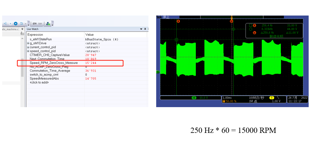
- 参考资料
https://www.nxp.com/search?keyword=UM11029
登录后下载
评论