

一、SecondBootloader 简介
在 MCU 项目的开发中,有时候会有程序更新升级的需求,这时通常将程序拆分为 Bootloader 程序和 Application 程序。由于一般芯片厂商会在芯片出厂前往 ROM 里固化一段 Bootloader 引导程序,有时为了避免混淆,这里用户自己写的 Bootloader 也称为 SecondBootloader。
一般由 SecondBootloader 完成 Application 程序的更新和启动跳转,由 Application 完成应用功能。比如 SecondBootloader 执行完了之后,需要跳转到 Application 运行,下面我们要介绍的就是这里的地址跳转。
二、地址跳转的实现
可以通过函数指针的形式调用目的 Application 程序的 ResetHandler 函数,从而实现内存地址的跳转。
这里我们以 RT1050 EVK 为例,介绍 SecondBootloader 地址跳转功能。以下介绍基于 Keil,SDK 为 SDK_2_12_0_EVKB-IMXRT1050 版本,Flash 使用 EVK 的 QSPI Flash。
下图为初步的 Flash 空间规划,该 QSPI Flash 总空间为 8Mbytes,地址范围 0x60000000 ~ 0x60800000,我们使用前 0x100000 存放 SecondBootloader,再往后 0x100000 的空间存放 Application 代码。程序先执行 SecondBootloader,然后跳转至 App1 运行应用代码。
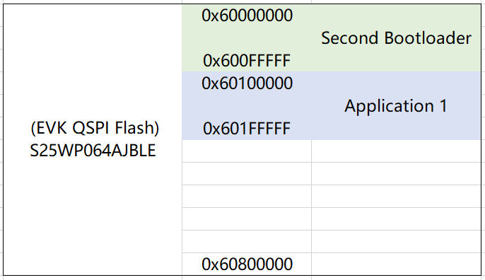
图 1. QSPI Flash 空间规划
2.1 跳转函数
下图为 SecondBootloader 中的跳转函数,入口参数给的是要跳转到的 Application 的起始地址。以上面的 Flash 空间规划为例,这里入口参数就是 App1 的起始地址,即 appStartAddress = 0x60100000。
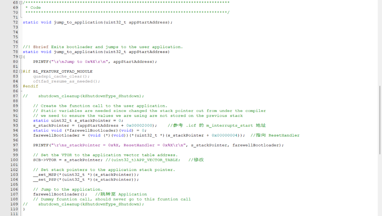
图2. 跳转函数
① 首先,我们要将中断向量表映射到 App1 的中断向量表的起始地址,即将新的中断向量表地址赋给内核寄存器 VTOR。
s_stackPointer = (appStartAddress + 0x00002000);

// Set the VTOR to the application vector table address.
SCB->VTOR = s_stackPointer;
可能有人会疑惑为什么赋给 VTOR 的值要在 App1 起始地址的基础上往后偏移 0x00002000 字节,这是因为 RT1052 代码的中断向量表并不是放在代码起始地址的,而是往后偏移了一段,开头留出来了一段 0x00002000 Bytes 的空间,这里面存放了 flash_config、IVT (Image Vector Table)、DCD (Device Configuration Data) 等数据,这点从 .icf 文件的空间分配上可以看出来。

图3.分散加载文件
② 然后,设置堆栈指针,将其赋值为 App1 的堆栈指针的初始值,该值一般存储于中断向量表的首个 4 字节内。
// Set stack pointers to the application stack pointer.
__set_MSP(*(uint32_t *)(s_stackPointer));
__set_PSP(*(uint32_t *)(s_stackPointer));
图4.向量表
③ 最后,是跳转到 App1 运行,这里跳转的地址应为 ResetHandler 的地址,该地址存储于中断向量表的第二个 4 字节内。跳转可用函数指针的形式实现,将函数指针指向 ResetHandler,然后通过调用指针的形式调用函数,即通过此方式将 PC 指针指向 ResetHandler。
farewellBootloader = (void (*)(void))(*(uint32_t *)(s_stackPointer + 0x00000004));  //指向 ResetHandler

// Jump to the application.
farewellBootloader();     //跳转至 Application
以上就是整个跳转函数的实现过程,我们在需要跳转的地方直接调用该函数即可。
2.2分散加载文件配置
由于我们要同时下载 SecondBootloader 和 App1 两个代码,这里需要配置一下 .icf 文件,将各代码放入图 1 规划的空间中。
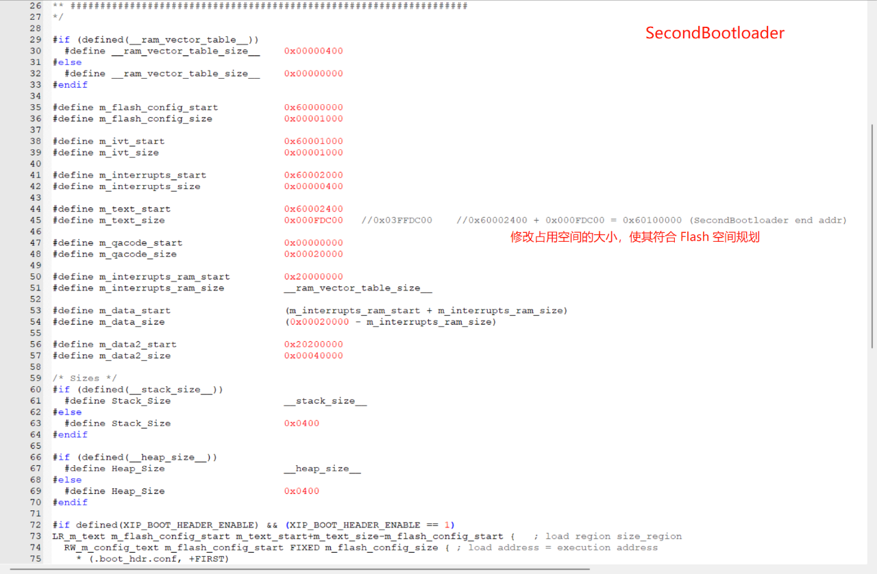
图 5. SecondBootloader icf 文件修改
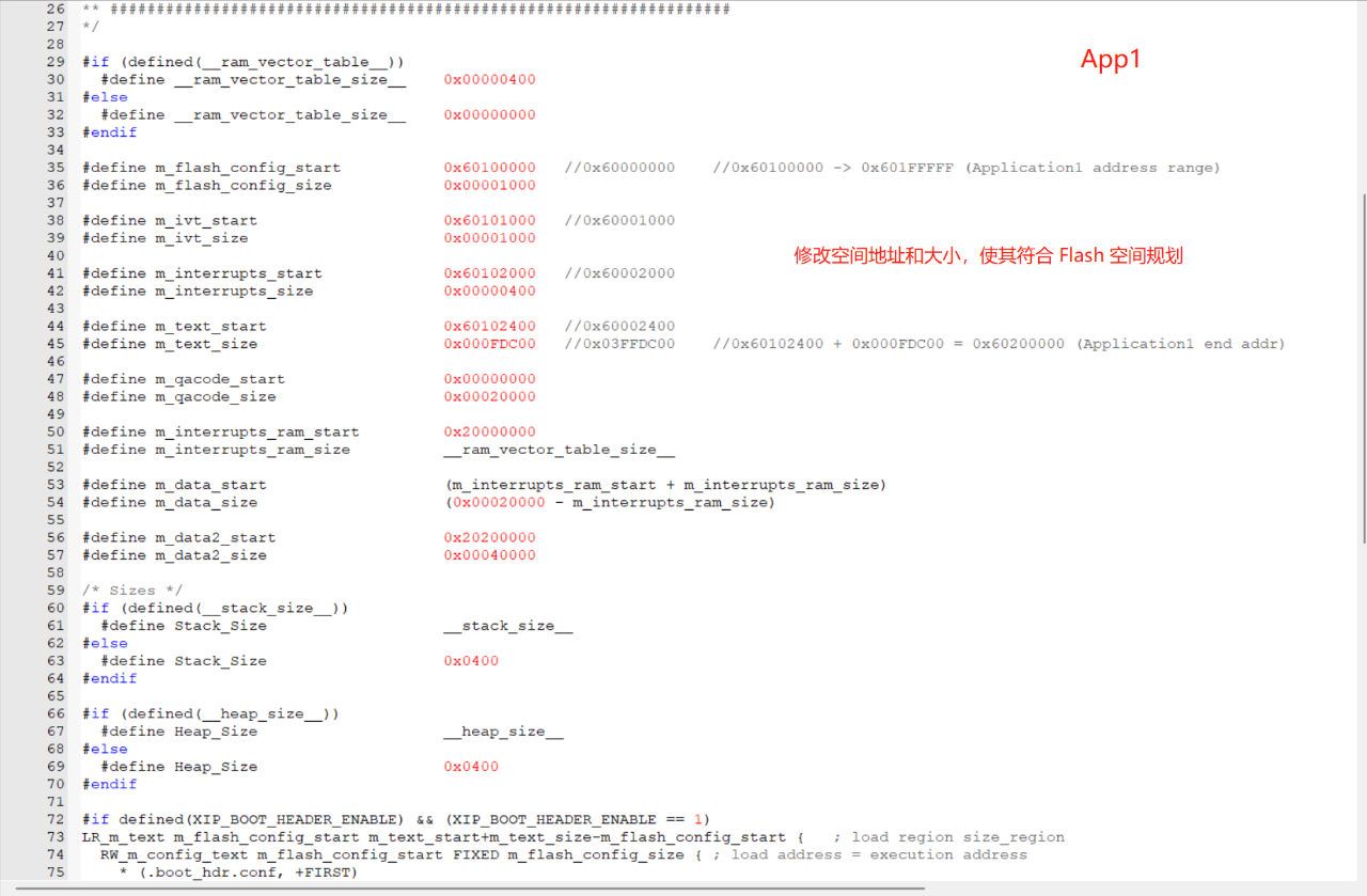
图 6. App1 icf 文件修改
2.3 Keil 下载配置
下载时,需配置各代码只擦写划分给自己的 Flash 区域,可在 Keil 下载设置中配置。

图 7. SecondBootloader 下载配置
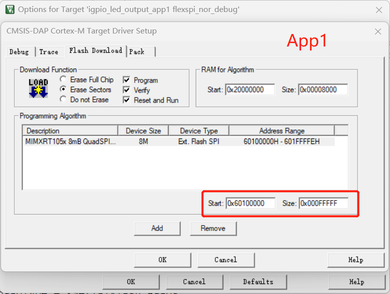
图 8. App1 下载配置
配置完成后就可以下载验证了!
2.4 运行现象
这里我们是在 SecondBootloader 中等待接受单个字符,接收到任意字符之后会跳转至 App1 运行闪灯程序,完整代码如第三章节所示。
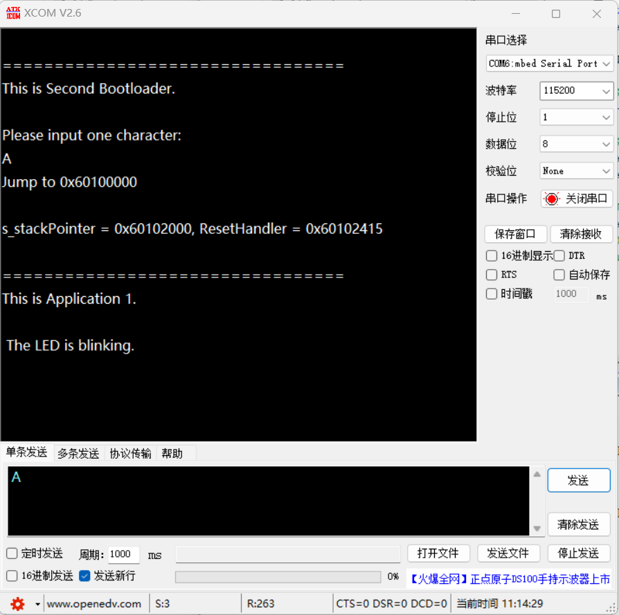
图 9. 运行现象
2.5 调试 App1
有时想验证 App1 能否正常运行时,也可以通过设置 Keil 的 .ini 文件来实现 Debug,修改 PC 指针、SP 指针和中断向量表偏移地址即可,如下图。

图 10. Debug 设置
三、实验代码
3.1 SecondBootloader 代码
/*
 * Copyright (c) 2015, Freescale Semiconductor, Inc.
 * Copyright 2016-2020 NXP
 * All rights reserved.
 *
 * SPDX-License-Identifier: BSD-3-Clause
 */

#include "pin_mux.h"
#include "clock_config.h"
#include "board.h"
#include "fsl_debug_console.h"
#include "fsl_gpio.h"

/*******************************************************************************
 * Definitions
 ******************************************************************************/

//-------------------------------- QSPI Flash range --------------------------------
//Start :  0x60000000
//End   :  0x61000000 (W25Q128JWSQ)	//0x60800000 (EVK S25WP064AJBLE)

//-------------------------------- Second Bootloader address --------------------------------
#define    SECONDBOOTLOADER_FLASH_START    0x60000000	//0x60000000 -> 0x600FFFFF = 0x00100000

//-------------------------------- Application 1 address --------------------------------
#define	   APP1_FLASH_START    0x60100000				//0x60100000 -> 0x601FFFFF = 0x00100000
#define    APP1_VECTOR_TABLE    (APP1_FLASH_START + 0x00002000)

////-------------------------------- Application 2 address --------------------------------
//#define	   APP2_FLASH_START    0x60200000				//0x60200000 -> 0x602FFFFF = 0x00100000
//#define    APP2_VECTOR_TABLE    (APP2_FLASH_START + 0x00002000)


#define EXAMPLE_LED_GPIO     BOARD_USER_LED_GPIO
#define EXAMPLE_LED_GPIO_PIN BOARD_USER_LED_GPIO_PIN

/*******************************************************************************
 * Prototypes
 ******************************************************************************/
/*******************************************************************************
* Variables
******************************************************************************/
/* The PIN status */
volatile bool g_pinSet = false;
/*******************************************************************************
* Code
******************************************************************************/
static void jump_to_application(uint32_t appStartAddress);
//! @brief Exits bootloader and jumps to the user application.
static void jump_to_application(uint32_t appStartAddress)
{
PRINTF("\r\nJump to 0x%X\r\n", appStartAddress);
#if BL_FEATURE_OTFAD_MODULE
quadspi_cache_clear();
oftfad_resume_as_needed();
#endif
// shutdown_cleanup(kShutdownType_Shutdown);
// Create the function call to the user application.
// Static variables are needed since changed the stack pointer out from under the compiler
// we need to ensure the values we are using are not stored on the previous stack
static uint32_t s_stackPointer = 0;
s_stackPointer = (appStartAddress + 0x00002000); //参考 .icf 的 m_interrupts_start 地址
static void (*farewellBootloader)(void) = 0;
farewellBootloader = (void (*)(void))(*(uint32_t *)(s_stackPointer + 0x00000004)); //指向 ResetHandler
PRINTF("\r\ns_stackPointer = 0x%X, ResetHandler = 0x%X\r\n", s_stackPointer, farewellBootloader);
// Set the VTOR to the application vector table address.
SCB->VTOR = s_stackPointer; //(uint32_t)APP_VECTOR_TABLE; //修改
// Set stack pointers to the application stack pointer.
__set_MSP(*(uint32_t *)(s_stackPointer));
__set_PSP(*(uint32_t *)(s_stackPointer));
// Jump to the application.
farewellBootloader(); //跳转至 Application
// Dummy fcuntion call, should never go to this fcuntion call
// shutdown_cleanup(kShutdownType_Shutdown);
}
/*!
* @brief Main function
*/
int main(void)
{
char ch;
/* Define the init structure for the output LED pin*/
gpio_pin_config_t led_config = {kGPIO_DigitalOutput, 0, kGPIO_NoIntmode};
/* Board pin, clock, debug console init */
BOARD_ConfigMPU();
BOARD_InitBootPins();
BOARD_InitBootClocks();
BOARD_InitDebugConsole();
/* Print a note to terminal. */
PRINTF("\r\n=================================\r\n");
PRINTF("This is Second Bootloader.\r\n");
/* Init output LED GPIO. */
GPIO_PinInit(EXAMPLE_LED_GPIO, EXAMPLE_LED_GPIO_PIN, &led_config);
PRINTF("\r\nPlease input one character:\r\n");
while (1)
{
ch = GETCHAR();
PUTCHAR(ch);
jump_to_application(APP1_FLASH_START);
}
}
3.2 Application1 代码
/*
 * Copyright (c) 2015, Freescale Semiconductor, Inc.
 * Copyright 2016-2020 NXP
 * All rights reserved.
 *
 * SPDX-License-Identifier: BSD-3-Clause
 */

#include "pin_mux.h"
#include "clock_config.h"
#include "board.h"
#include "fsl_debug_console.h"
#include "fsl_gpio.h"

/*******************************************************************************
 * Definitions
 ******************************************************************************/

//-------------------------------- QSPI Flash range --------------------------------
//Start :  0x60000000
//End   :  0x61000000 (W25Q128JWSQ)	//0x60800000 (EVK S25WP064AJBLE)

//-------------------------------- Second Bootloader address --------------------------------
#define    SECONDBOOTLOADER_FLASH_START    0x60000000	//0x60000000 -> 0x600FFFFF = 0x00100000

//-------------------------------- Application 1 address --------------------------------
#define	   APP1_FLASH_START    0x60100000				//0x60100000 -> 0x601FFFFF = 0x00100000
#define    APP1_VECTOR_TABLE    (APP1_FLASH_START + 0x00002000)

////-------------------------------- Application 2 address --------------------------------
//#define	   APP2_FLASH_START    0x60200000				//0x60200000 -> 0x602FFFFF = 0x00100000
//#define    APP2_VECTOR_TABLE    (APP2_FLASH_START + 0x00002000)


#define EXAMPLE_LED_GPIO     BOARD_USER_LED_GPIO
#define EXAMPLE_LED_GPIO_PIN BOARD_USER_LED_GPIO_PIN

/*******************************************************************************
 * Prototypes
 ******************************************************************************/

/*******************************************************************************
 * Variables
 ******************************************************************************/
/* The PIN status */
volatile bool g_pinSet = false;
/*******************************************************************************
 * Code
 ******************************************************************************/


/*!
 * @brief Main function
 */
int main(void)
{
    /* Define the init structure for the output LED pin*/
    gpio_pin_config_t led_config = {kGPIO_DigitalOutput, 0, kGPIO_NoIntmode};

    /* Board pin, clock, debug console init */
    BOARD_ConfigMPU();
    BOARD_InitBootPins();
    BOARD_InitBootClocks();
    BOARD_InitDebugConsole();

    /* Print a note to terminal. */

    PRINTF("\r\n=================================\r\n");
    PRINTF("This is Application 1.\r\n");
    PRINTF("\r\n The LED is blinking.\r\n");

    /* Init output LED GPIO. */
    GPIO_PinInit(EXAMPLE_LED_GPIO, EXAMPLE_LED_GPIO_PIN, &led_config);

    while (1)
    {
        SDK_DelayAtLeastUs(100000, SDK_DEVICE_MAXIMUM_CPU_CLOCK_FREQUENCY);
        GPIO_PortToggle(EXAMPLE_LED_GPIO, 1u << EXAMPLE_LED_GPIO_PIN);
    }
}
四、参考资料
(1)IMXRT1050RM.pdf
https://www.nxp.com/webapp/sps/download/preDownload.jsp?render=true
(2)博客《从MCU上电启动流程出发编写bootloader(上)》,网址: