

1. 用于步进电机的 PWM 斩波介绍
前面的博文介绍了此节的内容,本文将不再重复,可以搜索博文《使用 LPC5536 的 eFlexPWM 外设生成用于步进电机的 PWM 斩波》。
2. LPC5536 SCT 外设特性介绍和初始化代码
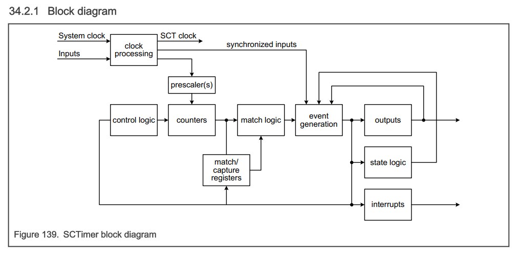
可以把 LPC5536 中的 SCTimer(state control Timer) 看成半定制的定时器, SCTimer 是一个功能强大、灵活的定时器模块,能够创建复杂的 PWM 波形,并在最少或无需 CPU 干预的情况下执行其他高级定时和控制操作。
SCT 可以作为单个 32 位计数器操作,也可以作为两个独立的 16 位计数器在单向或双向模式下操作。与大多数定时器一样,SCT 支持选择可与计数值进行比较的匹配寄存器,以及在检测到某些预定义条件时可记录当前计数值的捕获寄存器。SCT 模块支持多个单独的事件,
这些事件可以由用户根据一些参数组合来定义,包括一个匹配寄存器上的匹配、和/或一个 SCT 输入或输出上的变化,每个 SCT 模块有 8 个输入,10 个输出,16 个比较寄存器,16 个事件寄存器,16 个状态寄存器,SCT 模块的框图如下,本例中只用到他的 Output 输出功能。
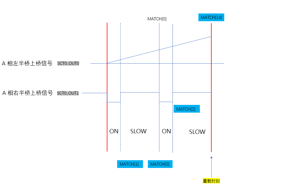
下图是步进电机其中一相的 H 桥的 PWM 信号,由 SCT 的 SCT0_OUT0 和 SCT0_OUT1 输出。
匹配寄存器 MATCH[14] 定义了 PWM 的频率,counter 计数到 MATCH[14] 时其将重新计数,同时拉低所有的 IO 信号, MATCH[1] 定义上半周 PWM 拉高的位置, MATCH[0] 定义了半周期的时刻,一般放在整个 PWM 周期的中点,当 counter 计数到 MATCH[0] 时拉低 PWM 信号。
MATCH[2] 定义下半周 PWM 信号拉高的时刻,直到计数到 MATCH[14],如此重复。当 counter 计数到对应的匹配寄存器时产生事件, SCT0_OUT0 或 SCT0_OUT1 绑定到此事件并定义是拉低还是拉高以此生成所需要的 PWM 信号。
各寄存器影响 PWM 波形如下图所示:
初始化代码:
通过设置 MATCH 寄存器不同的值即可改变 PWM 不同的占空比。
/*
AUTOLIMIT = 0
32bit: UNIFY = 1
unidirectional: BIDIR = 0
counter limit event: 14

*/
void SCT0_PWM_Unidirectional_Init(void)
{
	volatile uint32_t temp;

  /* Enable the SCTimer clock*/
  SYSCON->AHBCLKCTRLSET[1] = (1UL << 2UL);

  /* Reset the module. */
  SYSCON->PRESETCTRLSET[1] = (1UL << 2UL);
  while(0UL == (SYSCON->PRESETCTRL1 & 0x4UL))
  {
    /* ... */
  }
  SYSCON->PRESETCTRLCLR[1] = (1UL << 2UL);
  while(0x4UL == (SYSCON->PRESETCTRL1 & 0x4UL))
  {
    /* ... */
  }

  /* SCT CLK Configure */
  SYSCON->SCTCLKSEL = (SYSCON->SCTCLKSEL & 0xFFFFFFF8UL);//main_clock

	temp  = SCT0->CONFIG;
	temp &= 0xFFF80000;
  temp |= (1UL << 0UL)|  /* UNIFY = 1 */
					(0UL << 1UL)|  /* PWM clock mode:
											        0x0 System Clock Mode
											        0x1 Sampled System Clock Mode
											        0x2 SCT Input Clock Mode
											        0x3 Asynchronous Mode */
					(8UL << 3UL)|  /* CKSEL */
					(0UL << 7UL)|  /* NORELAOD_L */
					(0UL << 8UL)|  /* NORELAOD_H */
					(0UL << 9UL)|  /* INSYNC:Synchronization for input N */
					(0UL << 17UL)| /* AUTOLIMIT_L */
					(0UL << 18UL); /* AUTOLIMIT_H */

	SCT0->CONFIG = temp;


	temp  = SCT0->CTRL;
	temp &= 0xE000E000;
  temp |= (0UL << 1UL)|   /* STOP_L */
				  (1UL << 2UL)|   /* HALT_L */
				  (0UL << 3UL)|   /* CLRCTR_L */
				  (0UL << 4UL)|   /* BIDIR_L */
				  (0UL << 5UL);   /* PRE_L */
	SCT0->CTRL = temp;

  // Setup the LIMIT register
  // No events serve as counter limits because we are using the AUTOLIMIT feature of match0 (see the CONFIG reg. config.)
  // event 14
	SCT0->LIMIT = 1UL << 14UL;
  /* MATCH 14 */
  /* Sync eFlexPWM0, Delay 0° Clear eFlexPWM0 SM[0] Counter */
  SCT0->MATCH[14]    = (uint32_t)(MCU_CLOCK_FREQ/M1_PWM_FREQ - 1UL);
  SCT0->MATCHREL[14] = (uint32_t)(MCU_CLOCK_FREQ/M1_PWM_FREQ - 1UL);
  /*  Event 14, for counter LIMIT event */
	temp  = SCT0->EV[14].CTRL;
	temp &= 0xFF800000;
  temp |= (14UL << 0UL)|   /* MATCHSEL  select MATCH register */
				  (0UL << 4UL)|    /* HEVENT    Select L/H counter. Do not set this bit if UNIFY = 1 */
				  (0UL << 5UL)|    /* OUTSEL    Input 0/output 1 select */
				  (0UL << 6UL)|    /* IOSEL     Selects the input or output signal number */
				  (0UL << 10UL)|   /* IOCOND    Selects the I/O condition for event n, 00 Low,01 Rise,10 Fall,11 High */
				  (0x01UL<< 12UL)| /* COMBMODE  Selects how the specified match and I/O condition are used and combined. 01 match Only */
				  (0x0UL << 14UL)| /* STATELD   STATEV value is added (0) or loaded (1) into STATE */
				  (0x0UL << 15UL)| /* STATEV    This value is loaded into or added to the state */
				  (0x0UL << 20UL)| /* MATCHMEM  If this bit is zero, a match is only be active during the cycle */
				  (0x0UL << 21UL); /* DIRECTION BIDIR mode,0 Direction independent.1 Counting up.2 Counting down. */
  SCT0->EV[14].CTRL = temp;

  // Setup the HALT register
  // No events will set the HALT_L bit in the CTRL reg.
  SCT0->HALT = 0UL;

  // Setup the STOP register
  // No events will set the STOP_L bit in the CTRL reg.
  SCT0->STOP = 0UL;

	// Setup the START register
  // No events will set the START bit in the CTRL reg.
  SCT0->START = 0UL;

  // Initialize the COUNT register
  // Start counting at '0'
  SCT0->COUNT = 0UL;

  // Initialize the STATE register
  // Start in state 0
  SCT0->STATE = 0UL;

	//Dither Condition
  SCT0->DITHER = 0UL;

  // Setup the REGMODE register
  // 0x0 All Match/Capture registers act as match registers
  SCT0->REGMODE = 0x0UL;

  // Configure the OUTPUT register
  // Initialize CTOUT_x  to '0' ,software can write to any of the output registers when both counters are halted
  SCT0->OUTPUT = 0UL;

  // Configure the OUTPUTDIRCTRL register
	// 01 Set and clear are reversed when counter L or the unified counter is counting down
	// 00 Set and clear do not depend on the direction of any counter
	temp  = SCT0->OUTPUTDIRCTRL;
	temp &= 0xFFF00000;
  temp |= (0x1UL << 0UL)|  //output0,
					(0x1UL << 2UL)|  //output1,
					(0x1UL << 4UL)|  //output2,
					(0x1UL << 6UL)|  //output3,
					(0x1UL << 8UL)|  //output4,
					(0x1UL << 10UL)| //output5,
					(0x1UL << 12UL)| //output6,
					(0x1UL << 14UL)| //output7,
					(0x1UL << 16UL)| //output8,
					(0x1UL << 18UL); //output9,
  SCT0->OUTPUTDIRCTRL = temp;

  // Configure the RES register
  SCT0->RES = 0xFFFFFUL;// A Clear output,F Toggle output

  // Configure the SCT DMA register
  SCT0->DMAREQ0 = 0UL;
  SCT0->DMAREQ1 = 0UL;

  // Configure the event interrupt enable register
  SCT0->EVEN |= ((1UL << 9UL)|(1UL << 14UL));//(1UL << 14UL) event 14 requests an interrupt
  // Clear any pending event flags by writing '1's to the EVFLAG register
  SCT0->EVFLAG = 0xFFFFUL;

  // Configure the conflict interrupt enable register
  SCT0->CONEN |= 0b1111111111;//
  // Clear any pending 'no-change conflict' event flags, and BUSSERR flags, by writing '1's to the CONLAG register
  SCT0->CONFLAG |= (0x3 << 30UL) | (0b1111111111);

  // Configure the match registers (and their associated match reload registers, which will be the same for this example)
  // for the PWM duty cycles desired
  //150Mhz/36621KHz/2 = 2048
  SCT0->MATCH[0]    = (uint32_t)(MCU_CLOCK_FREQ/M1_PWM_FREQ/2UL - 1UL);   // Match0 is the AUTOLIMIT event, determines the period of the PWM
  SCT0->MATCHREL[0] = (uint32_t)(MCU_CLOCK_FREQ/M1_PWM_FREQ/2UL - 1UL);   //

  /* MATCH 15 */
  SCT0->MATCH[15]    = (uint32_t)(MCU_CLOCK_FREQ/M1_PWM_FREQ/2UL);
  SCT0->MATCHREL[15] = (uint32_t)(MCU_CLOCK_FREQ/M1_PWM_FREQ/2UL);

  /* PWM1 */
  SCT0->MATCH[1]    = (uint32_t)(MCU_CLOCK_FREQ/M1_PWM_FREQ + 1UL);//0% Duty
  SCT0->MATCHREL[1] = (uint32_t)(MCU_CLOCK_FREQ/M1_PWM_FREQ + 1UL);//0% Duty

  /* PWM2 */
  SCT0->MATCH[2]    = (uint32_t)(MCU_CLOCK_FREQ/M1_PWM_FREQ + 1UL);//0% Duty
  SCT0->MATCHREL[2] = (uint32_t)(MCU_CLOCK_FREQ/M1_PWM_FREQ + 1UL);//0% Duty

  /* PWM3 */
  SCT0->MATCH[3]    = (uint32_t)(MCU_CLOCK_FREQ/M1_PWM_FREQ + 1UL);//0% Duty
  SCT0->MATCHREL[3] = (uint32_t)(MCU_CLOCK_FREQ/M1_PWM_FREQ + 1UL);//0% Duty

  /* PWM4 */
  SCT0->MATCH[4]    = (uint32_t)(MCU_CLOCK_FREQ/M1_PWM_FREQ + 1UL);//0% Duty
  SCT0->MATCHREL[4] = (uint32_t)(MCU_CLOCK_FREQ/M1_PWM_FREQ + 1UL);//0% Duty

  /* PWM5 */
  SCT0->MATCH[5]    = (uint32_t)(MCU_CLOCK_FREQ/M1_PWM_FREQ + 1UL);//0% Duty
  SCT0->MATCHREL[5] = (uint32_t)(MCU_CLOCK_FREQ/M1_PWM_FREQ + 1UL);//0% Duty

  /* PWM6 */
  SCT0->MATCH[6]    = (uint32_t)(MCU_CLOCK_FREQ/M1_PWM_FREQ + 1UL);//0% Duty
  SCT0->MATCHREL[6] = (uint32_t)(MCU_CLOCK_FREQ/M1_PWM_FREQ + 1UL);//0% Duty

  /* PWM7 */
  SCT0->MATCH[7]    = (uint32_t)(MCU_CLOCK_FREQ/M1_PWM_FREQ + 1UL);//0% Duty
  SCT0->MATCHREL[7] = (uint32_t)(MCU_CLOCK_FREQ/M1_PWM_FREQ + 1UL);//0% Duty

  /* PWM8 */
  SCT0->MATCH[8]    = (uint32_t)(MCU_CLOCK_FREQ/M1_PWM_FREQ + 1UL);//0% Duty
  SCT0->MATCHREL[8] = (uint32_t)(MCU_CLOCK_FREQ/M1_PWM_FREQ + 1UL);//0% Duty

  /* MATCH 10 */
  SCT0->MATCH[10]    = (uint32_t)(MCU_CLOCK_FREQ/M1_PWM_FREQ + 1UL);//0% Duty
  SCT0->MATCHREL[10] = (uint32_t)(MCU_CLOCK_FREQ/M1_PWM_FREQ + 1UL);//0% Duty

  /* MATCH 11 */
  SCT0->MATCH[11]    = (uint32_t)(MCU_CLOCK_FREQ/M1_PWM_FREQ + 1UL);//0% Duty
  SCT0->MATCHREL[11] = (uint32_t)(MCU_CLOCK_FREQ/M1_PWM_FREQ + 1UL);//0% Duty

  /* MATCH 12 */
  SCT0->MATCH[12]    = (uint32_t)(MCU_CLOCK_FREQ/M1_PWM_FREQ + 1UL);//0% Duty
  SCT0->MATCHREL[12] = (uint32_t)(MCU_CLOCK_FREQ/M1_PWM_FREQ + 1UL);//0% Duty

  /* MATCH 13 */
  SCT0->MATCH[13]    = (uint32_t)(MCU_CLOCK_FREQ/M1_PWM_FREQ + 1UL);//0% Duty
  SCT0->MATCHREL[13] = (uint32_t)(MCU_CLOCK_FREQ/M1_PWM_FREQ + 1UL);//0% Duty

  /* Event is enabled in state 0 - 15,setting bit 0 permanently enables this event */
  /* Only work at state 0 */
  SCT0->EV[0].STATE = 0x1UL;
  SCT0->EV[1].STATE = 0x1UL;
  SCT0->EV[2].STATE = 0x1UL;
  SCT0->EV[3].STATE = 0x1UL;
  SCT0->EV[4].STATE = 0x1UL;
  SCT0->EV[5].STATE = 0x1UL;
  SCT0->EV[6].STATE = 0x1UL;
  SCT0->EV[7].STATE = 0x1UL;
  SCT0->EV[8].STATE = 0x1UL;
  SCT0->EV[9].STATE = 0x1UL;
  SCT0->EV[10].STATE = 0x1UL;
  SCT0->EV[11].STATE = 0x1UL;
  SCT0->EV[12].STATE = 0x1UL;
  SCT0->EV[13].STATE = 0x1UL;
  SCT0->EV[14].STATE = 0x1UL;
  SCT0->EV[15].STATE = 0x1UL;

  /*  Event 0 */
	temp  = SCT0->EV[0].CTRL;
	temp &= 0xFF800000;
  temp |= (0UL << 0UL)|    /* MATCHSEL  select MATCH register */
				  (0UL << 4UL)|    /* HEVENT    Select L/H counter. Do not set this bit if UNIFY = 1 */
				  (0UL << 5UL)|    /* OUTSEL    Input 0/output 1 select */
				  (0UL << 6UL)|    /* IOSEL     Selects the input or output signal number */
				  (0UL << 10UL)|   /* IOCOND    Selects the I/O condition for event n, 00 Low,01 Rise,10 Fall,11 High */
				  (0x01UL<< 12UL)| /* COMBMODE  Selects how the specified match and I/O condition are used and combined. 01 match Only */
				  (0x0UL << 14UL)| /* STATELD   STATEV value is added (0) or loaded (1) into STATE */
				  (0x0UL << 15UL)| /* STATEV    This value is loaded into or added to the state */
				  (0x0UL << 20UL)| /* MATCHMEM  If this bit is zero, a match is only be active during the cycle */
				  (0x0UL << 21UL); /* DIRECTION BIDIR mode,0 Direction independent.1 Counting up.2 Counting down. */
  SCT0->EV[0].CTRL = temp;

  /*  Event 1,PWM1 */
	temp  = SCT0->EV[1].CTRL;
	temp &= 0xFF800000;
  temp |= (1UL << 0UL)|    /* MATCHSEL  select MATCH register */
				  (0UL << 4UL)|    /* HEVENT    Select L/H counter. Do not set this bit if UNIFY = 1 */
				  (0UL << 5UL)|    /* OUTSEL    Input 0/output 1 select */
				  (0UL << 6UL)|    /* IOSEL     Selects the input or output signal number */
				  (0UL << 10UL)|   /* IOCOND    Selects the I/O condition for event n, 00 Low,01 Rise,10 Fall,11 High */
				  (0x01UL<< 12UL)| /* COMBMODE  Selects how the specified match and I/O condition are used and combined. 01 match Only */
				  (0x0UL << 14UL)| /* STATELD   STATEV value is added (0) or loaded (1) into STATE */
				  (0x0UL << 15UL)| /* STATEV    This value is loaded into or added to the state */
				  (0x0UL << 20UL)| /* MATCHMEM  If this bit is zero, a match is only be active during the cycle */
				  (0x0UL << 21UL); /* DIRECTION BIDIR mode,0 Direction independent.1 Counting up.2 Counting down. */
  SCT0->EV[1].CTRL = temp;

  /*  Event 2,PWM2 */
	temp  = SCT0->EV[2].CTRL;
	temp &= 0xFF800000;
  temp |= (2UL << 0UL)|    /* MATCHSEL  select MATCH register */
				  (0UL << 4UL)|    /* HEVENT    Select L/H counter. Do not set this bit if UNIFY = 1 */
				  (0UL << 5UL)|    /* OUTSEL    Input 0/output 1 select */
				  (0UL << 6UL)|    /* IOSEL     Selects the input or output signal number */
				  (0UL << 10UL)|   /* IOCOND    Selects the I/O condition for event n, 00 Low,01 Rise,10 Fall,11 High */
				  (0x01UL<< 12UL)| /* COMBMODE  Selects how the specified match and I/O condition are used and combined. 01 match Only */
				  (0x0UL << 14UL)| /* STATELD   STATEV value is added (0) or loaded (1) into STATE */
				  (0x0UL << 15UL)| /* STATEV    This value is loaded into or added to the state */
				  (0x0UL << 20UL)| /* MATCHMEM  If this bit is zero, a match is only be active during the cycle */
				  (0x0UL << 21UL); /* DIRECTION BIDIR mode,0 Direction independent.1 Counting up.2 Counting down. */
  SCT0->EV[2].CTRL = temp;

  /*  Event 3,PWM3 */
	temp  = SCT0->EV[3].CTRL;
	temp &= 0xFF800000;
  temp |= (3UL << 0UL)|    /* MATCHSEL  select MATCH register */
				  (0UL << 4UL)|    /* HEVENT    Select L/H counter. Do not set this bit if UNIFY = 1 */
				  (0UL << 5UL)|    /* OUTSEL    Input 0/output 1 select */
				  (0UL << 6UL)|    /* IOSEL     Selects the input or output signal number */
				  (0UL << 10UL)|   /* IOCOND    Selects the I/O condition for event n, 00 Low,01 Rise,10 Fall,11 High */
				  (0x01UL<< 12UL)| /* COMBMODE  Selects how the specified match and I/O condition are used and combined. 01 match Only */
(0x0UL << 14UL)| /* STATELD STATEV value is added (0) or loaded (1) into STATE */
(0x0UL << 15UL)| /* STATEV This value is loaded into or added to the state */
(0x0UL << 20UL)| /* MATCHMEM If this bit is zero, a match is only be active during the cycle */
(0x0UL << 21UL); /* DIRECTION BIDIR mode,0 Direction independent.1 Counting up.2 Counting down. */
SCT0->EV[3].CTRL = temp;
/* Event 4,PWM4 */
temp = SCT0->EV[4].CTRL;
temp &= 0xFF800000;
temp |= (4UL << 0UL)| /* MATCHSEL select MATCH register */
(0UL << 4UL)| /* HEVENT Select L/H counter. Do not set this bit if UNIFY = 1 */
(0UL << 5UL)| /* OUTSEL Input 0/output 1 select */
(0UL << 6UL)| /* IOSEL Selects the input or output signal number */
(0UL << 10UL)| /* IOCOND Selects the I/O condition for event n, 00 Low,01 Rise,10 Fall,11 High */
(0x01UL<< 12UL)| /* COMBMODE Selects how the specified match and I/O condition are used and combined. 01 match Only */
(0x0UL << 14UL)| /* STATELD STATEV value is added (0) or loaded (1) into STATE */
(0x0UL << 15UL)| /* STATEV This value is loaded into or added to the state */
(0x0UL << 20UL)| /* MATCHMEM If this bit is zero, a match is only be active during the cycle */
(0x0UL << 21UL); /* DIRECTION BIDIR mode,0 Direction independent.1 Counting up.2 Counting down. */
SCT0->EV[4].CTRL = temp;
/* Event 5,PWM5 */
temp = SCT0->EV[5].CTRL;
temp &= 0xFF800000;
temp |= (5UL << 0UL)| /* MATCHSEL select MATCH register */
(0UL << 4UL)| /* HEVENT Select L/H counter. Do not set this bit if UNIFY = 1 */
(0UL << 5UL)| /* OUTSEL Input 0/output 1 select */
(0UL << 6UL)| /* IOSEL Selects the input or output signal number */
(0UL << 10UL)| /* IOCOND Selects the I/O condition for event n, 00 Low,01 Rise,10 Fall,11 High */
(0x01UL<< 12UL)| /* COMBMODE Selects how the specified match and I/O condition are used and combined. 01 match Only */
(0x0UL << 14UL)| /* STATELD STATEV value is added (0) or loaded (1) into STATE */
(0x0UL << 15UL)| /* STATEV This value is loaded into or added to the state */
(0x0UL << 20UL)| /* MATCHMEM If this bit is zero, a match is only be active during the cycle */
(0x0UL << 21UL); /* DIRECTION BIDIR mode,0 Direction independent.1 Counting up.2 Counting down. */
SCT0->EV[5].CTRL = temp;
/* Event 6,PWM6 */
temp = SCT0->EV[6].CTRL;
temp &= 0xFF800000;
temp |= (6UL << 0UL)| /* MATCHSEL select MATCH register */
(0UL << 4UL)| /* HEVENT Select L/H counter. Do not set this bit if UNIFY = 1 */
(0UL << 5UL)| /* OUTSEL Input 0/output 1 select */
(0UL << 6UL)| /* IOSEL Selects the input or output signal number */
(0UL << 10UL)| /* IOCOND Selects the I/O condition for event n, 00 Low,01 Rise,10 Fall,11 High */
(0x01UL<< 12UL)| /* COMBMODE Selects how the specified match and I/O condition are used and combined. 01 match Only */
(0x0UL << 14UL)| /* STATELD STATEV value is added (0) or loaded (1) into STATE */
(0x0UL << 15UL)| /* STATEV This value is loaded into or added to the state */
(0x0UL << 20UL)| /* MATCHMEM If this bit is zero, a match is only be active during the cycle */
(0x0UL << 21UL); /* DIRECTION BIDIR mode,0 Direction independent.1 Counting up.2 Counting down. */
SCT0->EV[6].CTRL = temp;
/* Event 7,PWM7 */
temp = SCT0->EV[7].CTRL;
temp &= 0xFF800000;
temp |= (7UL << 0UL)| /* MATCHSEL select MATCH register */
(0UL << 4UL)| /* HEVENT Select L/H counter. Do not set this bit if UNIFY = 1 */
(0UL << 5UL)| /* OUTSEL Input 0/output 1 select */
(0UL << 6UL)| /* IOSEL Selects the input or output signal number */
(0UL << 10UL)| /* IOCOND Selects the I/O condition for event n, 00 Low,01 Rise,10 Fall,11 High */
(0x01UL<< 12UL)| /* COMBMODE Selects how the specified match and I/O condition are used and combined. 01 match Only */
(0x0UL << 14UL)| /* STATELD STATEV value is added (0) or loaded (1) into STATE */
(0x0UL << 15UL)| /* STATEV This value is loaded into or added to the state */
(0x0UL << 20UL)| /* MATCHMEM If this bit is zero, a match is only be active during the cycle */
(0x0UL << 21UL); /* DIRECTION BIDIR mode,0 Direction independent.1 Counting up.2 Counting down. */
SCT0->EV[7].CTRL = temp;
/* Event 8,PWM8 */
temp = SCT0->EV[8].CTRL;
temp &= 0xFF800000;
temp |= (8UL << 0UL)| /* MATCHSEL select MATCH register */
(0UL << 4UL)| /* HEVENT Select L/H counter. Do not set this bit if UNIFY = 1 */
(0UL << 5UL)| /* OUTSEL Input 0/output 1 select */
(0UL << 6UL)| /* IOSEL Selects the input or output signal number */
(0UL << 10UL)| /* IOCOND Selects the I/O condition for event n, 00 Low,01 Rise,10 Fall,11 High */
(0x01UL<< 12UL)| /* COMBMODE Selects how the specified match and I/O condition are used and combined. 01 match Only */
(0x0UL << 14UL)| /* STATELD STATEV value is added (0) or loaded (1) into STATE */
(0x0UL << 15UL)| /* STATEV This value is loaded into or added to the state */
(0x0UL << 20UL)| /* MATCHMEM If this bit is zero, a match is only be active during the cycle */
(0x0UL << 21UL); /* DIRECTION BIDIR mode,0 Direction independent.1 Counting up.2 Counting down. */
SCT0->EV[8].CTRL = temp;
/*
SCT_OUT4 ---> PWM0 EXT_Sync
NO AUTOLIMIT:
EVENT 9(MATCH[9]) ---> SCT_OUT4 Fall
EVENT 14(MATCH[14]) ---> SCT_OUT4 Rise
*/
SCT0->MATCH[9] = (uint32_t)(MCU_CLOCK_FREQ/M1_PWM_FREQ/2UL - 1UL);
SCT0->MATCHREL[9] = (uint32_t)(MCU_CLOCK_FREQ/M1_PWM_FREQ/2UL - 1UL);
/* Event 9, Sync eFlexPWM0 */
temp = SCT0->EV[9].CTRL;
temp &= 0xFF800000;
temp |= (9UL << 0UL)| /* MATCHSEL select MATCH register */
(0UL << 4UL)| /* HEVENT Select L/H counter. Do not set this bit if UNIFY = 1 */
(0UL << 5UL)| /* OUTSEL Input 0/output 1 select */
(0UL << 6UL)| /* IOSEL Selects the input or output signal number */
(0UL << 10UL)| /* IOCOND Selects the I/O condition for event n, 00 Low,01 Rise,10 Fall,11 High */
(0x01UL<< 12UL)| /* COMBMODE Selects how the specified match and I/O condition are used and combined. 01 match Only */
(0x0UL << 14UL)| /* STATELD STATEV value is added (0) or loaded (1) into STATE */
(0x0UL << 15UL)| /* STATEV This value is loaded into or added to the state */
(0x0UL << 20UL)| /* MATCHMEM If this bit is zero, a match is only be active during the cycle */
(0x0UL << 21UL); /* DIRECTION BIDIR mode,0 Direction independent.1 Counting up.2 Counting down. */
SCT0->EV[9].CTRL = temp;
/* SCT0_OUT4 */
SCT0->OUT[4].SET = (1UL << 14UL);
SCT0->OUT[4].CLR = (1UL << 9UL);
/* Event 10 */
temp = SCT0->EV[10].CTRL;
temp &= 0xFF800000;
temp |= (10UL << 0UL)| /* MATCHSEL select MATCH register */
(0UL << 4UL)| /* HEVENT Select L/H counter. Do not set this bit if UNIFY = 1 */
(0UL << 5UL)| /* OUTSEL Input 0/output 1 select */
(0UL << 6UL)| /* IOSEL Selects the input or output signal number */
(0UL << 10UL)| /* IOCOND Selects the I/O condition for event n, 00 Low,01 Rise,10 Fall,11 High */
(0x01UL<< 12UL)| /* COMBMODE Selects how the specified match and I/O condition are used and combined. 01 match Only */
(0x0UL << 14UL)| /* STATELD STATEV value is added (0) or loaded (1) into STATE */
(0x0UL << 15UL)| /* STATEV This value is loaded into or added to the state */
(0x0UL << 20UL)| /* MATCHMEM If this bit is zero, a match is only be active during the cycle */
(0x0UL << 21UL); /* DIRECTION BIDIR mode,0 Direction independent.1 Counting up.2 Counting down. */
SCT0->EV[10].CTRL = temp;
/* Event 11 */
temp = SCT0->EV[11].CTRL;
temp &= 0xFF800000;
temp |= (11UL << 0UL)| /* MATCHSEL select MATCH register */
(0UL << 4UL)| /* HEVENT Select L/H counter. Do not set this bit if UNIFY = 1 */
(0UL << 5UL)| /* OUTSEL Input 0/output 1 select */
(0UL << 6UL)| /* IOSEL Selects the input or output signal number */
(0UL << 10UL)| /* IOCOND Selects the I/O condition for event n, 00 Low,01 Rise,10 Fall,11 High */
(0x01UL<< 12UL)| /* COMBMODE Selects how the specified match and I/O condition are used and combined. 01 match Only */
(0x0UL << 14UL)| /* STATELD STATEV value is added (0) or loaded (1) into STATE */
(0x0UL << 15UL)| /* STATEV This value is loaded into or added to the state */
(0x0UL << 20UL)| /* MATCHMEM If this bit is zero, a match is only be active during the cycle */
(0x0UL << 21UL); /* DIRECTION BIDIR mode,0 Direction independent.1 Counting up.2 Counting down. */
SCT0->EV[11].CTRL = temp;
/* Event 12 */
temp = SCT0->EV[12].CTRL;
temp &= 0xFF800000;
temp |= (12UL << 0UL)| /* MATCHSEL select MATCH register */
(0UL << 4UL)| /* HEVENT Select L/H counter. Do not set this bit if UNIFY = 1 */
(0UL << 5UL)| /* OUTSEL Input 0/output 1 select */
(0UL << 6UL)| /* IOSEL Selects the input or output signal number */
(0UL << 10UL)| /* IOCOND Selects the I/O condition for event n, 00 Low,01 Rise,10 Fall,11 High */
(0x01UL<< 12UL)| /* COMBMODE Selects how the specified match and I/O condition are used and combined. 01 match Only */
(0x0UL << 14UL)| /* STATELD STATEV value is added (0) or loaded (1) into STATE */
(0x0UL << 15UL)| /* STATEV This value is loaded into or added to the state */
(0x0UL << 20UL)| /* MATCHMEM If this bit is zero, a match is only be active during the cycle */
(0x0UL << 21UL); /* DIRECTION BIDIR mode,0 Direction independent.1 Counting up.2 Counting down. */
SCT0->EV[12].CTRL = temp;
/* Event 13 */
temp = SCT0->EV[13].CTRL;
temp &= 0xFF800000;
temp |= (13UL << 0UL)| /* MATCHSEL select MATCH register */
(0UL << 4UL)| /* HEVENT Select L/H counter. Do not set this bit if UNIFY = 1 */
(0UL << 5UL)| /* OUTSEL Input 0/output 1 select */
(0UL << 6UL)| /* IOSEL Selects the input or output signal number */
(0UL << 10UL)| /* IOCOND Selects the I/O condition for event n, 00 Low,01 Rise,10 Fall,11 High */
(0x01UL<< 12UL)| /* COMBMODE Selects how the specified match and I/O condition are used and combined. 01 match Only */
(0x0UL << 14UL)| /* STATELD STATEV value is added (0) or loaded (1) into STATE */
(0x0UL << 15UL)| /* STATEV This value is loaded into or added to the state */
(0x0UL << 20UL)| /* MATCHMEM If this bit is zero, a match is only be active during the cycle */
(0x0UL << 21UL); /* DIRECTION BIDIR mode,0 Direction independent.1 Counting up.2 Counting down. */
SCT0->EV[13].CTRL = temp;
/* Event 15 */
temp = SCT0->EV[15].CTRL;
temp &= 0xFF800000;
temp |= (15UL << 0UL)| /* MATCHSEL select MATCH register */
(0UL << 4UL)| /* HEVENT Select L/H counter. Do not set this bit if UNIFY = 1 */
(0UL << 5UL)| /* OUTSEL Input 0/output 1 select */
(0UL << 6UL)| /* IOSEL Selects the input or output signal number */
(0UL << 10UL)| /* IOCOND Selects the I/O condition for event n, 00 Low,01 Rise,10 Fall,11 High */
(0x01UL<< 12UL)| /* COMBMODE Selects how the specified match and I/O condition are used and combined. 01 match Only */
(0x0UL << 14UL)| /* STATELD STATEV value is added (0) or loaded (1) into STATE */
(0x0UL << 15UL)| /* STATEV This value is loaded into or added to the state */
(0x0UL << 20UL)| /* MATCHMEM If this bit is zero, a match is only be active during the cycle */
(0x0UL << 21UL); /* DIRECTION BIDIR mode,0 Direction independent.1 Counting up.2 Counting down. */
SCT0->EV[15].CTRL = temp;
/* Configure the OUT registers for the SCT outputs */
/* selects event m to set output n,bit 0 with event 0, etc.). */
/* PWM1 OUT0 */
SCT0->OUT[0].SET = 0UL;
SCT0->OUT[0].CLR = 0UL;
/* PWM2 OUT1 */
SCT0->OUT[1].SET = 0UL;
SCT0->OUT[1].CLR = 0UL;
//PWM3 OUT2
SCT0->OUT[2].SET = 0UL;
SCT0->OUT[2].CLR = 0;
/* PWM4 OUT3 */
SCT0->OUT[3].SET = 0UL;
SCT0->OUT[3].CLR = 0UL;
/* PWM5 OUT5 */
SCT0->OUT[5].SET = 0UL;
SCT0->OUT[5].CLR = 0UL;
/* PWM6 OUT6 */
SCT0->OUT[6].SET = 0UL;
SCT0->OUT[6].CLR = 0UL;
/* PWM7 OUT7 */
SCT0->OUT[7].SET = 0UL;
SCT0->OUT[7].CLR = 0UL;
/* PWM8 OUT8 */
SCT0->OUT[8].SET = 0UL;
SCT0->OUT[8].CLR = 0UL;
/* OUT9 */
SCT0->OUT[9].SET = 0UL;
SCT0->OUT[9].CLR = 0UL;
/* FINALLY ... now let's run it. Clearing bit 2 of the CTRL register takes it out of HALT. */
SCT0->CTRL &= (uint32_t)(~(1UL << 2UL)); /* HALT_L = 0,START COUNTER */
// NVIC_SetPriority (SCT0_IRQn, 0UL);
// NVIC_EnableIRQ(SCT0_IRQn);
}
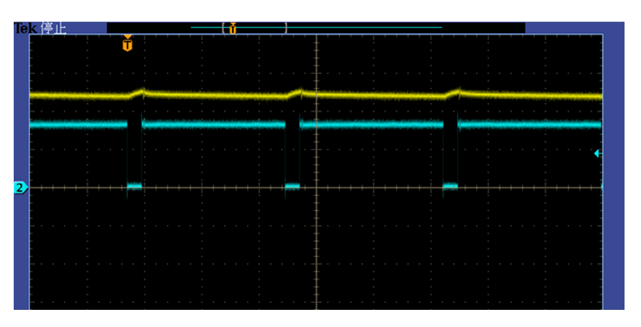
3. 实际效果
以上是使用 SCT生成需要的 PWM 的波形的过程,在完整的步进电机控制中这种 PWM 斩波模式可以实现比较好的电流波形,纹波比较小,蓝色为 PWM 信号,黄色为电流信号。
4. 参考文档
LPC5536 参考手册:
https://www.nxp.com.cn/docs/en/reference-manual/LPC553xRM.pdf